Heat Pumps
A heat pump is a device which extracts heat from a source that is normally at too low a temperature to be used directly, making it available as useful heat at a higher temperature. Typical sources are heat rejected as process effluent, cooling water, humid air or warm fluid from a chilling process. In addition heat sources at or below ambient temperature can be used, examples being the air, the ground or river water. Heat loads include air and water for space heating or various process fluids such as hot water for washing and hot air for drying. The heat pump can be used to greatest advan tage when the temperature lift and the required load temperature are lowest.
Compared to conventional 'passive' heat recovery, the heat pump has three important characteristics:
- It is used for temperature upgrading rather than simple heat recovery; the heat pump can therefore extend the temperature range over which waste heat is recoverable.
- High grade energy is necessary to drive the heat pump so the extra heat is produced at some cost; it is therefore better to think of the heat pump as an efficient heating system rather than a heat recovery device.
- Heat pumps are essentially limited to applications involving temperatures below about 1200C.
Types of Heat Pump
The most common heat pump operating cycle employs vapour compression which uses the mechani cal energy for temperature elevation. There are alternative cycles such as absorption involving a physical chemistry process for temperature elevation, together with modified thermodynamic cycles and thermoelectric processes which are only at the development stage. Only the vapour compression heat pump is considered here because units of this type are more readily available and are likely to be no more costly than the equivalent absorption units.
Vapour compression heat pumps have been designed to operate according to a number of thermo dynamic cycles such as those due to Rankine, Otto, Brayton or Stirling. The ideal Carnot efficiency is most closely approached by the Rankine cycle and hence this offers the best performance prospects. Consequently, currently available electric motor and gas engine driven heat pumps employ this cycle. The components used are readily available from air conditioning and refrigeration practice.
The Vapour Compression Cycle
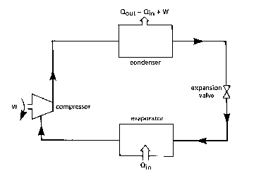
The vapour compression cycle has the advantage that it is proven technology, offering a relatively high efficiency over a reasonable range of temperatures. The basic system is shown in Figure 1 and consists of a compressor, expansion device and two heat exchangers.
Fig.1 Components used in the vapour compression heat pump
- The cycle is closed and the working fluid is commonly a refrigerant such as Freon operating in two phases. A description of the operation, starting with the evaporator, is as follows:
- The temperature of the working fluid in the evaporator is lower than the temperature of the source. Heat is therefore transferred to the working fluid causing it to evaporate.
- The evaporated vapour is then drawn into the compressor and, by the input of shaft power, is compressed to a higher pressure and temperature.
- The vapour leaving the compressor and entering the condenser is at a temperature higher than that of the load to be heated. During its passage through the condenser, therefore, heat is rejected to the load causing the working fluid to condense.
- The high pressure liquid then passes through an expansion device where its pressure and hence temperature are lowered. Low temperature fluid then enters the evaporator to com plete the cycle.
A range of refrigerant working fluids are available commercially such as R22, R12 and R1 14 for low, medium and high temperature applications respectively. Although some heat pumps have operated at temperatures in excess of 120 0C, most are at present limited to less than about 70 0C at the condenser.
In practice, a heat pump contains more components than are shown in the diagrams although these do not greatly affect the basic heat pump cycle. A number of compressor types are available such as reciprocating, sliding vane, screw and centrifugal. Reciprocating compressors are currently the most common but other types are becoming more popular for heat pump applications.
Gas Engine Driven Heat Pumps
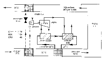
While heat pumps are commonly driven by electric motors, an alternative is to use a reciprocating, spark ignition, internal combustion engine operating on natural gas - see Figure 2. The principal advantage of the gas engine is that while shaft power is produced at about the same cost as with the electric motor, a quantity of high grade heat corresponding to about 55% of the energy input can be recovered from the engine jacket and exhaust system. This heat can be used to supplement the heat pump condenser output, resulting in several advantages. First, the size of the heat pump components (compressor, condenser, etc.) will be smaller for a given total heat output for a gas engine heat pump (GEHP) than for an electric motor heat pump (EMHP). Second, the maximum load outlet temperature will be higher for a given refrigerant system design. Alternatively, for a fixed outlet temperature, a higher efficiency will be achieved due to the engine heat providing part of the temperature lift. In cases where heat is required at two distinct levels, an example might be warm air at 45 0C, the GEHP could provide both efficiently. A further advantage is the speed modulation which provides for improved heat pump control and heat output modulation with minimal loss of efficiency.
Fig. 2 Schematic of the Gas Engine Driven Heat Pump
Heat Pump Performance
Heat pump performance has historically been expressed as the Coefficient of Performance (COP) which is defined as the heat output from the condenser divided by the power required to drive the compressor. COP is of limited value when considering the performance of a heat pump installation since it does not take into account the efficiency of the compressor drive, power for ancillaries or heat supplied by the engine. For this reason, another term, the Performance Effectiveness Ratio (PER), is used and this is defined as:
PER          = useful heat output from the complete installation
                                energy input to the installation
The PER allows the customer to determine directly the cost of energy delivered by the heat pump based on the unit costs for the input energy (electricity or gas), and thus allows the cost savings compared to other plant to be calculated.
The values of COP and PER for both electric motor heat pumps and gas engine heat pumps vary with the temperature difference between the load and source. PER has the higher value for the gas engine type since part of the temperature lift is being provided by the engine heat recovery. COP is the greater of the two ratios for the electric motor type but it would need to be three or four times as great, as is the typical cost of electricity in relation to that of gas, to achieve the same running costs.
Economics
The economics of heat pumps are affected by the annual energy cost savings achieved, maintenance costs and the capital cost. The annual energy cost savings are a function of a number of factors such as the PER actually achieved, the efficiency of the base heating plant, operating hours and energy prices. Maintenance for gas engine heat pumps has been found to be typically 10% of the engine fuel consumption cost. Capital costs are dependent on the application, rating, ease of incorporation into existing plant, whether or not a developed packaged unit can be used and whether the heat pump is part of a large scheme.
To achieve the best economic case, as many as possible of the following criteria should be satisfied:
- Long operating hours at steady demand.
- Low temperature lifts.
- Moderate upper temperature.
- Matched heat demand and supply of waste heat.
- Existing plant in need of replacement due to age or poor efficiency.
- Conventional heat recovery equipment not suitable.
- Heat demand in excess of minimum economic size (e.g. at least 80 kW for gas engine heat pump).
If most of these criteria can be substantially met, then Performance Effectiveness Ratios of 1.5 to 3.0 can be practically achieved on systems incorporating some passive heat recovery. This equates to energy savings of about 50% to 75%, depending on the efficiency of the previous system. The construction and installation of gas engine heat pumps, although leaning heavily on refrigeration practice, has been well developed now for several years. It is probable that higher performances can be achieved and that there is scope to reduce installed costs. Both of these effects should come about as the market develops and the number sold increases. Dependent upon the trend in future fuel prices, further development should reduce the current payback periods of 3 to 5 years significantly.
Gas Engine Driven Heat Pump Applications
Due to the relatively high capital cost of heat pump installations, they are only economically attractive in applications where long hours of operation and moderate temperature differences can be assured.
Heat pumps have been applied as a means of heat recovery where a low grade source waste heat is of temperature below that required for re-use in part of a process. As discussed, the heat pump is used to elevate temperatures, for example, in a dairy where milk cooling yields low temperature water which can be upgraded for bottle washing. The maximum load temperature from the condenser for a heat pump is around 70 0C when using ambient air at -1 0C as the source. However, where warm effluent is available at say 70 0C then condensing temperatures of 120 0C are achievable.
Heat pump recovery systems have also been installed on heating and dehumidification applications, for example in drying processes and swimming pools.
A specific example is a malt drying kiln (Figure 3) where the source and sink may be some distance apart and where the heat extracted by the evaporator is principally latent heat. The heat collected at the evaporator is elevated by the compressor to a temperature of 60 0C at the condenser. The resultant warmed supply air temperature to the kiln is subsequently raised to 72 0C by exhaust and water jacket heat recovery.
Figure 3
For more information contact Mearsecroft
Created and updated by Spiders Webs